


By definition, permanent electrical insulating joints (connections or couplings) are maintenance-free and non-demountable products and shall ensure mechanical and dielectrical properties during their whole life cycle.
The main function of an electrical insulating joint is prevention of protection potential reduction caused by leakages:
- Through the metal pipeline
- Through the transported product
- Through the surrounding soil.
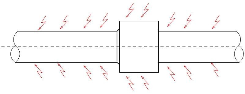
Potential leakages through a metal pipeline
The basic leakages are those through a metal pipeline. The use of electrical insulating joints in this case will be particularly effective. At that, apart from ensuring good insulation, an electrical insulating joint must guarantee excellent mechanical sealing against internal pressure and the capacity of withstanding mechanical loads: bending, tension and torsion transferred by the pipeline.
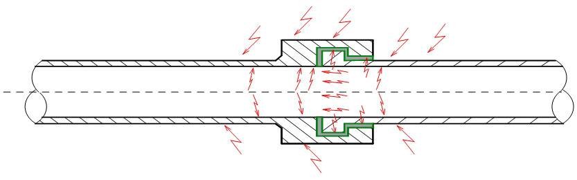
A permanent electrical insulating joint with the use of a transverse insulation system prevents potential leakages in the pipeline.
Potential leakages through the transported product
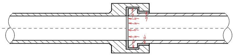
Leakages though the pipeline, having met an obstacle in the form of an electrical insulating joint, can take place through the transported product. This phenomenon becomes stronger if the transported product has a high conductivity.
Prevention of potential leakages through the transported product requires the use of a longitudinal internal insulation.
Potential leakages through the surrounding soil
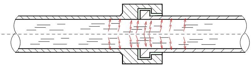
Leakages through the pipeline, having met an obstacle in the form of a permanent electrical insulating joint, can take place through the surrounding soil. This phenomenon becomes stronger if the soil has a low electrical resistance. Also, electrical currents of another nature can arise in the soil that can influence the cathodic protection system of the pipeline.
Prevention of potential leakages through the surrounding soil requires the use of a longitudinal external insulation.
Evolutionary development of the design of permanent electrical insulating joints
To prevent transported product leakages the electrical insulating joint should ensure excellent mechanical sealing against internal pressure and withstand different mechanical loads: bending, tension and torsion transferred by the pipeline. This depends on the coupling design and production technology.
1. The sealing system with the use of rubber round cross-section rings. It was designed in the 1960-1970s.
2. The sealing system with the use of rectangular cross-section gaskets. It was designed in the 1980s.
3. The sealing system made of composite materials. Its development began in the 1990s.
4. The U-shaped sealing system. It was designed in the 1990s.
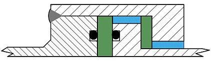
Sealing system with the use of round cross-section rubber rings (designed in the 1960-1970s)
Basically, the sealing system consists of 2 or 4 round cross-section rubber rings. It seals surfaces only between metal and the insulation ring. The given sealing system was based on that of insulation flanges.
Disadvantages:
- Due to a small length of the sealing surface in case of use of round cross-section rubber rings high-quality finishing of sealing surfaces is required, which is achieved only by grinding and polishing.
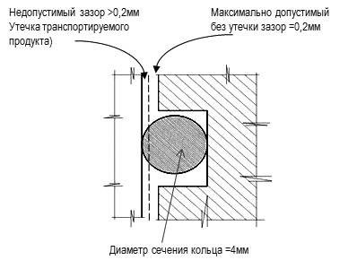
- In static conditions the ring destruction takes place owing to expelling into the sealing gap. The value of the permissible sealing gap equals to several tenths of a millimeter.
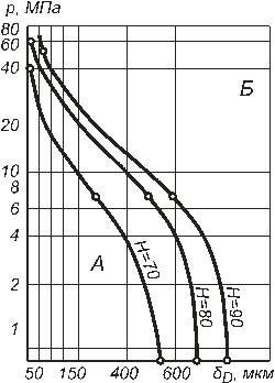 Diagram 1. The relationship between
the rubber sealing ring expelling pressure
and the diametral gap and hardness of rubber
Sealing system with the use of round cross-section rubber rings (designed in 1960-1970s)
Since to prevent the phenomenon of explosive decompression (with subsequent formation of microcracks in the sealing ring material) the dimensions of round cross-section rubber rings are small, the structure deformation by several tenths of a millimeter is enough for occurrence of a transported product leakage (for example: as little as 0.2 mm for a rubber ring with cross section of 4 mm). For example, longitudinal deformations of a permanent electrical insulating joint DN 400 with wall thickness of 15 mm, strength class К60 caused only by loading with internal pressure of 150 kgf/cm2(excluding bending loads) are above 0.3 mm.
 Double sealing system with the use of round cross-section rubber rings
To reduce the impact of the specified design drawbacks of a sealing system with the use of round cross-section rubber rings, manufacturers add the second or auxiliary sealing system, the actual purpose of which is to deal with the inefficiency of the main sealing system.
However, this solution does not make it possible to overcome a whole series of problems related with reduction of dielectrical properties of permanent electrical insulating joints caused by penetration of the transported product into the internal cavity of the structure.
Because of the above mentioned, there are the following restrictions:
- by the capacity of permanent electrical insulating joints to withstand structural deformations under impact of bending, tension stresses and torque;
- by the capacity to withstand high pressures.
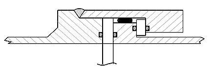
Sealing system with the use of rectangular cross-section gaskets (designed in the 1980s)
The sealing system represents a single sealing gasket of rectangular cross section located, in pre-compressed state, between metal surfaces and the metal and the insulation ring surface.
This sealing system is specially designed for permanent electrical insulating joints.
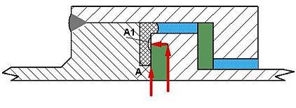
Disadvantages:
During operation it is essential to take into account the bending moment acting on the electrical insulating joint.
In fact, the pressure acts on the gasket in A and A1 points, which leads to the following:
- a bending moment increase causes a swell on the sealing gasket surface;
- longitudinal tension stresses caused by the impact of high operating pressure increase;
- the distortion of the gasket surface in A1 point reduces the size of the contact sealing surface.
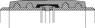
Sealing system for electrical insulating joints made of composite materials (start of development in the 1990s)
The sealing system is developed in Russia. It represents a combination of a special sealing gasket and round cross-section rubber rings.
 Destruction of an insulation gasket
Disadvantages
- Special equipment for sealing gasket manufacturing and assembly is required.
- The first stage of the sealing system (with rubber rings) has all the disadvantages characteristic for sealing systems with the use of round cross-section rubber rings.
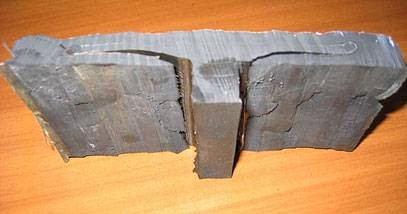
 Crack in composite shell
- The use of a composite pressure shell as the second stage of the sealing system has additional restrictions related to significantly greater (comparing to a metal pressure structure) deformations for the same values of internal pressure, bending moment and torque, tension force, which can lead to gasket destruction owing to formation of cracks and ruptures.
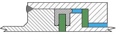
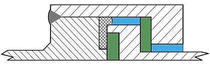
U-shaped sealing system (designed in the 1990s) of permanent electrical insulating joints
This sealing system represents a U-shaped double-profile gasket placed around the insulation ring, tightly compressed in the sealing nest formed by the metal surfaces. This sealing system was specially designed for permanent electrical insulating joints and it is usually called a double gasket sealing system.
Disadvantages
- Special equipment for manufacturing and assembly is required.
Advantages
- High-quality finishing of sealing surfaces and observation of very accurate machining tolerances are not required.
- The sealing surfaces are both those between the metal and the insulation ring surface and those between the metal surfaces.
- A very long sealing surface and large cross section enable withstanding significantly greater structural deformations (tension, bending) comparing to sealing systems with the use of rectangular cross-section gaskets and especially comparing to the use of round cross-section rubber rings.
- The possibility of explosive decompression is excluded as the gasket is in locked position and is fully surrounded by the sealing nest surfaces.
- There are no restrictions concerning the use of U-shaped gaskets in permanent electrical insulating joints. It is recommended for use in conditions of high pressures (up to 1,000 kgf/cm2) and increased external mechanical loads (tension, compression, bending moment and torque). It is capable of withstanding stresses and loads without loss of sealing similarly to the basic material of the pipeline.