


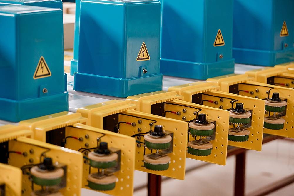
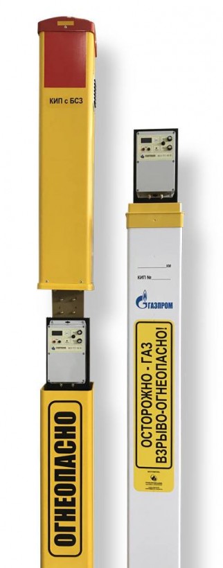
 Test station with RCU(R) for upstream
1.Resistance control unit (rheostat) RCU(R)
RCU(R) are designed to provide resistance control of parallel, converging, or intersecting underground steel structures and utilities by regulating the ECP parameters.
RCU(R) are used as a part of Test Stations produced according to the TS 3435-002-93719333-2009, TS 3435-008-93719333-2012, TBPSh.421453.028 TS and as a separate unit.
RCU (R) may be additionally equipped with CMS-PST for remote monitoring, storage and transfer of the corrosion protection parameters of buried steel construction.
 Cables installation on a terminal board
RCU (R) are recommended to apply at the linear part of the main pipelines and at industrial sites:
- at pipeline crossings;
- at the pipelines crossings with armored signal cables;
- at electrical insulating joints;
- at other sections of pipelines, in accordance with the requirements of GOST R 51164, GOST 9.602 and reference documentation of organizations operating underground pipelines.
- others
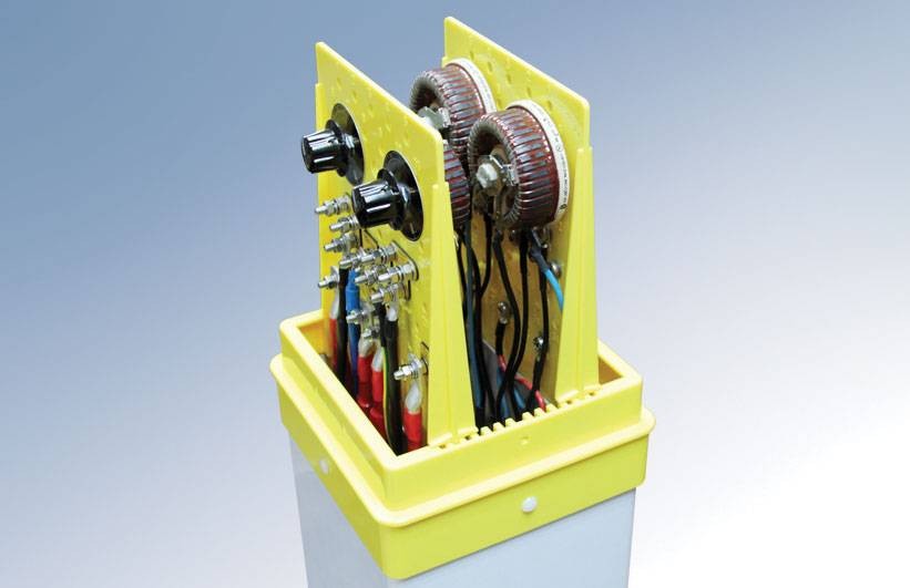
RCU(R) are manufactured in two versions:
- in a metal electrical cabinet;
- inside the TS post.
Power rheostats situated in the RCUs (R) allow to adjust the channel resistance smoothly without using electrical ¬jumpers and disconnecting the cathodic protection rectifier. Built-in shunt allows to determine the channel current rate with help of a millivoltmeter.
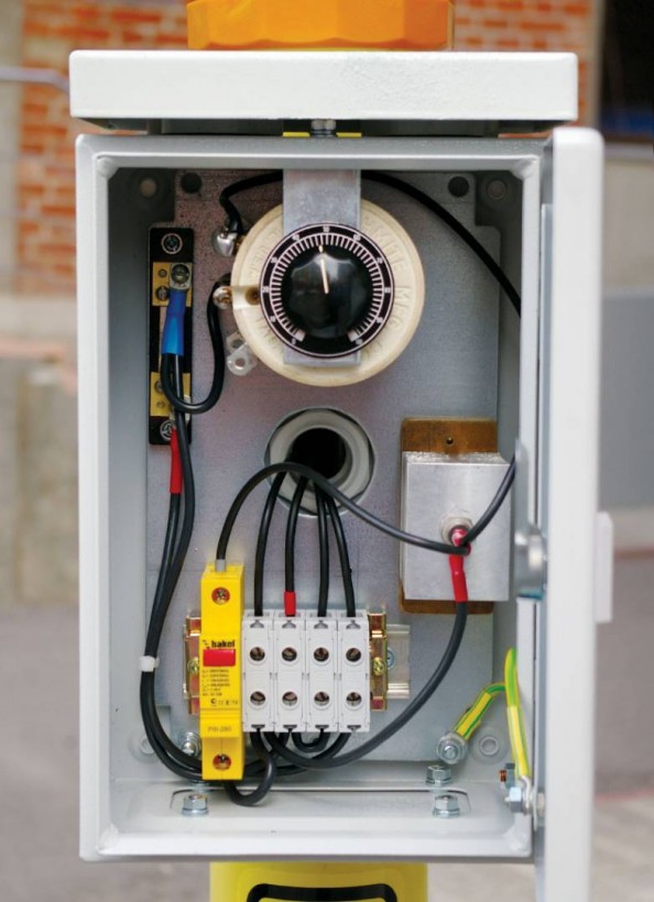
RCU (R) design in a metal electrical cabinet consists of the following:
- electric cabinet;
- terminal block;
- diodes;
- rheostats;
- instrument shunts..
TRCU (R) design in the terminal cabinet has the following characteristics:
| Max. current | Adjustment range of the rheostat electrical resistance |
| 1А | 0…30 Ohm |
| 2A | 0…30 Ohm |
| 10А | 0…0,5 Ohm |
| 15А | 0…0,5 Ohm |
| 25А | 0…0,25 Ohm |
| 30А | 0…0,25 Ohm |
The quantity of independent control channels is set by the Client in the purchase order data sheet.
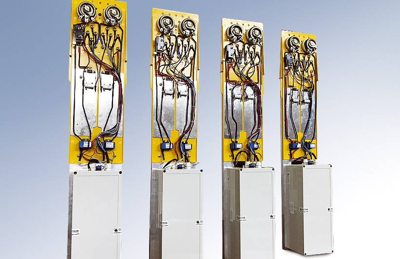
RCU (R) design on the terminal board consists of the following:
- TS terminal block;
- diodes;
- rheostats;
- instrument shunts;
- radiator;
- CMS-PST block (as an option).
 Four-channel RCU-14A
RCU (R) design on the terminal block has the following characteristics:
| Max. current | Adjustment range of the rheostat electrical resistance | Quantity of independent control channels |
| 1А | 0…30 Ohm | 1 … 4 |
| 10А | 0…0,5 Ohm | 1 … 4 |
| 15А | 0…0,5 Ohm | 1 … 4 |
| 25А | 0…0,25 Ohm | 1 |
| 30А | 0…0,25 Ohm | 1 |
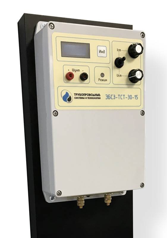
2. Electronic resistance control unit (ERCU)
ERCU Application field — Corrosion Protection Systems of Metal Structures
ERCUs are used in combined cathodic protection systems and depending on the version, may ensure simultaneous protection of several buried metal structures from one cathodic protection rectifier by distributing output current among protected structures and setting optimal protection current or potential for each protected structure separately.
The ERCU does not contain any built-in power supplies. The unit is powered by the potential difference between the protected structures.

The ERCU supports the following operation modes:
- current stabilization mode;
- potential difference stabilization mode.
ERCU legend
- product name;
- manufacturer name;
- nominal current;
- nominal potential difference;
- climatic version (U2).
An example of the ordered ERCU-PST with the nominal output current of 30 A and the nominal potential difference of 15 V: ERCU-PST-30-15-U2 TU
Basic technical characteristics
| Technical characteristics | Value |
|---|---|
| Maximum power dissipation, W | 150 |
| Stabilized current range, A | 0,5…30 1 |
| Maximum current within 10 minutes, A | 32 2 |
| Minimum potential difference in the current stabilization mode, V | 0,1 3 |
| Maximum potential difference in the current stabilization mode, V | 15 4 |
| Maximum stabilization error of the set current, % | 2,5 5 |
| Stabilized potential difference range, V | 0,5…12 |
| Maximum stabilization error of the set potential difference, % | 2,5 |
| Minimum potential difference for operation of the built-in indicator, V | 0,4 |
| Surge protection response voltage, V | 16 |
| Maximum voltage and current indication error, % | 5 |
| Overheating protection response temperature, °С | + 70 6 |
| Maximum reverse voltage, V | 100 |
| Maximum reverse current, A | |
| Climate version as per GOST 15150, in this case: | U2 |
| — operating temperature range, °С | - 45… + 60 7 |
| — relative air humidity at 25 °С, % | up to 98 |
| — atmospheric pressure, kPa | from 84,0 to 106,7 |
| — operation in the following types of atmosphere | I и II |
| Minimum transportation and storage temperature, °С | - 50 |
| Housing dimensions (without the radiator), mm, max. | 255х146х83 |
| Dimensions (with the radiator8 and control elements), mm, max. | 600х170х110 |
| Weight, kg, max. | 4 |
- In case the potential difference at the ERCU terminals is at least 250 mV, the radiator temperature does not exceed 70° С, and the power dissipation does not exceed 150 W.
- In case the potential difference at the ERCU terminals is at least 270 mV, the radiator temperature does not exceed 70° С, and the power dissipation does not exceed 150 W.
- With the specified potential difference value at the ERCU terminals, the current adjustment is possible up to 2 A; with the voltage of 0.15 V, up to 10 A; and with the voltage ranging from 0.25 V to 15 V, up to 30 A.
- In case the radiator temperature does not exceed 70° С, and the power dissipation does not exceed 150 W.
- In the range of the potential difference at the ERCU terminals from 0.25 V to 15 V, and absence of protection operation impact.
- The radiator temperature is controlled in immediate vicinity of load-bearing elements. Peripheral areas of the radiator may have lower temperature.
- As the ambient temperature increases, the maximum possible current and the maximum possible power dissipation of the ERCU will automatically lower to values at which the radiator temperature does not exceed 70 °C.
- The ERCU radiator may have different dimensions depending on the operating conditions, upon request and agreement with the Customer.